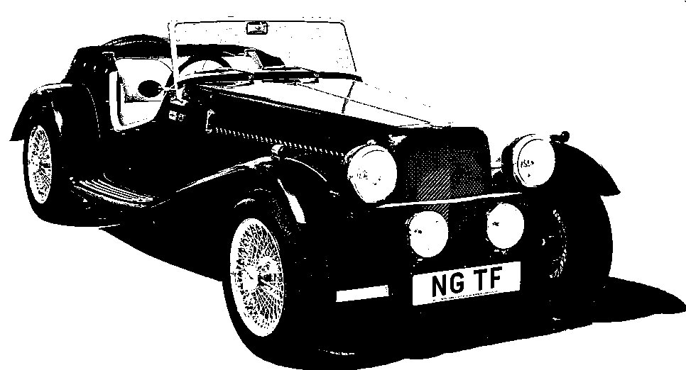
NG Kit Car
4.1 Chassis Particulars
Chassis Rubbers
Rubber strips are glued to the chassis using contact adhesive (photo 1). See the Chassis Diagrams for the area covered.
A wallpaper roller helps to press down the rubber once glued (photo 2). Notice the holes cut in the rubber (slightly oversize) in line with the bolt holes. A sharpened piece of 15mm copper tube was used for these.
Fitting Torque Braces
Two torque braces are supplied which mount between the chassis (cross-member fixing bolts) and the footwell front (photo 3). When positioning these, it must be remembered that the rear mounting plates should be faced with chassis rubber. A hole needed to be drilled in each brace forward mounting plate.
To find the correct centre, I first removed the 2 rearmost cross member mounting bolts and, with the brace and rubber in position, marked the chassis where the front end of the brace came to. I then carefully measured from here to the centre of the mounting hole in the chassis (with the brace removed) and transferred that measurement to the brace plate.
Chassis Number
One of the requirements of the SVA test is that the chassis number is permanently displayed on a fixed visible part of the chassis. The chassis number is provided by NG when supplying the chassis and this can be punched onto the top of a brace (photo 4). I found that a piece of wood, cramped to the brace and marked at 1/4" intervals helped to align the lettering.
Rubber Sleeve Inserts
Where the electrical cable, fuel pipe and brake pipes pass through the cross members of the chassis, something is needed to seal the holes and act as a sleeve. It is recommended that 50mm lengths of 1/2" heater hose is used but I found that these were extremely tight to fit.
So I cut the hose a little longer than recommended (about 65mm), made a slit down the length and took a slither out. I then cut the corners off one end to form a leading edge to feed through the chassis holes (photo 5). They can now be slid over the pipe or cable and eased into the holes, still providing a tight fit. The slit is best set at the top so that the hose acts as a gutter to keep any water from entering the chassis.

glued to chassis

rolled on to chassis

to protect pipes & cables

glued to chassis