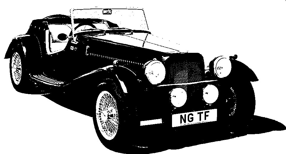
NG Kit Car
8.3 Handbrake
A new handbrake cable was attached at the rear end to the handbrake compensator assembly (having been repainted) and was then fitted to the differential housing (photo 1). These are standard MGB items.
Cable Route
The handbrake itself is mounted on a bracket on the top of the transmission tunnel. The route of the handbrake cable caused some head scratching! The basic problem is that it must cross the transmission tunnel without fouling the prop shaft. There is more than one route it could take and I looked at a number of options before making my decision as follows:
-
I used an MGB cable clip and attached it to the rear axle under the brake hose bracket. This holds the cable so that it points forwards and towards the centre of the vehicle (photo 2).
-
The cable then climbs up the right rear (offside) of the transmission tunnel and is held with a p-clip. (Note: in photo 3 the suspension is in its highest "hanging" position but care must be taken to allow for compression of the suspension.)
-
It then finishes along the roof of the transmission tunnel where the cable post is secured to the top left (nearside) of the tunnel (photo 4).
Midget Handbrake Modification
I later decided to replace the standard MGB handbrake with an MG Midget one which looks a little less obtrusive.
Photo 5 shows the MGB and Midget handbrakes. The Midget one is normally mounted from the other side but as I had already made the mounting for the MGB handbrake I decided to use the Midget one upside down (as is shown here) which required some modification. I reversed the ratchet by bending the rod the opposite way (circled in photo 5) and used the MGB ratchet pawl.
There remained two problems for the Midget handbrake to fit the MGB ratchet:
-
the spindle of the handbrake lever was too long and
-
the shoulders for the drop lever were the wrong angle
I very carefully cut the existing shoulders down to the same depth as the MGB handbrake and formed a new angled shoulder (see photo 6). I then filed the spindle and used a 3/8" UNF die to extend the thread. The end result can be seen in photo 7.
Incidentally, the handbrake warning light switch can also be seen in photo 7 just ahead of the ratchet mechanism.

compensator attached to differential

routed under rear axle

mounted

compensator attached to differential