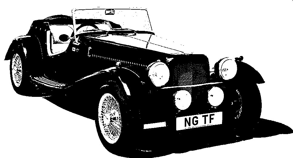
NG Kit Car
8.4 Pedals & Pedal Box
As suggested in the NG build manual, the brake pedal arm needed just a little crank to space out the pedals more evenly. I found an easy, controllable way was to place 3 punches in a vice (photo 1) and slowly tighten it. Doing this in two positions produced a gentle crank which "moved" the brake pedal over slightly to the left but kept the foot piece parallel to the clutch pedal.
New bushes were purchased for the pedals but these needed reaming by a helpful, local engineering company. A stop light switch is also supplied by NG and is fitted under the master cylinder in line with the brake pedal. A new cover was needed too and, of course, new pedal rubbers (photo 2).
Initially I used the brake switch as a stop for the brake pedal. This was not satisfactory because too much pedal travel was needed to operate the brake lights and it was not strong enough either. I therefore made a pedal stop out of a piece of steel angle (photo 3). I was then able to adjust the switch to just turn off with the pedal released.
It was also necessary to replace the supplied clear plastic hoses from the reservoir to the master cylinder with the correct braided type (photo 4).
Pedal Spring Bracket
To attach the pedal return springs, using some 15mm angle steel, I cut a bracket (see photo 5 for dimensions) which bolts inside the footwell to the underside of the pedal box using the rearmost bolts.
I later modified this slightly because the springs rubbed on the steering column bolts. So the 1/8" holes were re-drilled 10mm further out (110mm between centres).
In photo 6 the pedals have been fitted and the springs connected to the bracket. Note also the position of the accelerator bracket which bolts to the rear of the offside (right hand) torque brace fittings.

using a vice

assembled

showing modified hole position

using a vice
Click this icon for a PDF version of the Pedal Spring Bracket which you are free to download.