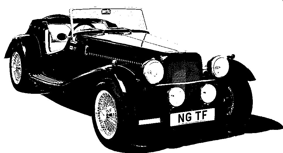
NG Kit Car
17.1 Wiring Looms
The supplied 3-piece wiring loom is designed to make the electrics easy and the colour coding is explained in the manual. I recommend taking time to study the loom and the associated diagrams so as to fully understand all its functions. While there are a few minor anomalies and modifications, in the main it saves a lot of time and head scratching. The main problem I found was deciding how best to route and secure the loom.
Dashboard Loom
This first section fits behind the dashboard. It carries the electric supply from a fuse link and fuse box to all the switches and instruments.
The fuse box is fitted to the nearside of the bulkhead (photo 1). I decided to mount the master fuse and relay sockets on the back of the bulkhead near the fuse box (photo 2). The dash loom connects to all of these.
There are 5 multi-way (Ripaults) connectors which link this loom to the other sections. The loom is fixed to the back of the dashboard using tie bases and cable ties (photos 3 & 4).
The following minor modifications were made:
-
A plug was fitted to the connectors for the hazard warning switch
-
The relay sockets were replaced as those supplied had insufficient room for the relays
-
An earth connector was fitted to the flasher unit socket
-
Extensions were added to reach the washer bottle
-
The loom was re-clipped to allow a longer section to reach the ignition switch
-
The tachometer connectors were modified to match the tachometer
Also the standard indicator switch plug was changed to match the (Ripaults) loom connector
Front Loom
This second section connects to the dashboard loom and serves the engine compartment, front lights, etc. It also brings the main feed from the starter motor to the main fuse link behind the dashboard.
The front loom was run in split convoluted tubing and fixed to tie bases on the footwell top & front and on the chassis rail (photo 5). I fitted another 3 tie bases on the rear of the front cross-member to take the loom across to the nearside of the vehicle and one on top under the radiator to take forward the wires to the horns and driving lamps (photo 6). A hole in each bonnet side panel was made to allow the loom to reach under each wing to service the lights.
Note: the red ties in the photos are temporary re-usable ones.
The following minor modifications were made:
-
The loom was re-clipped to allow a slightly longer section to reach the offside lights
-
The excess cable for a V8 coil was removed and a connector fitted (just in case it is ever needed!)
-
Convoluted tubing was used for added protection
-
An extension loom was made up for the coil which I sited on top of the footwell.
Rear Loom
This third section connects to the dash loom and serves the gearbox switches, handbrake switch, fuel pump, tank sender and rear lights.
The rear loom was run down and along the left-hand side of the body tub and fixed with p-clips (rear loom photo 1). The first split-off takes the wires through the side of the transmission tunnel for the gearbox switches. The second split-off feeds the handbrake switch. The third feeds the fuel pump and tank sender and the rest feed the rear lights.
The following minor modifications were made:
-
As it is difficult to reach the switches on the top of the gearbox, I made up a mini-loom to connect these with the rear loom.
-
To avoid having cable routed under a potential rear seat, I decided to run the fuel pump supply and tank sender wires underneath the body. They were run in convoluted sleeving and clipped to the chassis rail. (Note the body hole to be filled as a result - rear loom photo 2).
-
Small extensions were made for the fuel pump and the tank sender unit.
-
For the rear lights mounted in the wings, connections were made in the boot space (rear loom photo 2).

beside washer bottle

behind bulkhead

on cross-member

beside washer bottle

on left floor

on boot floor

on left floor