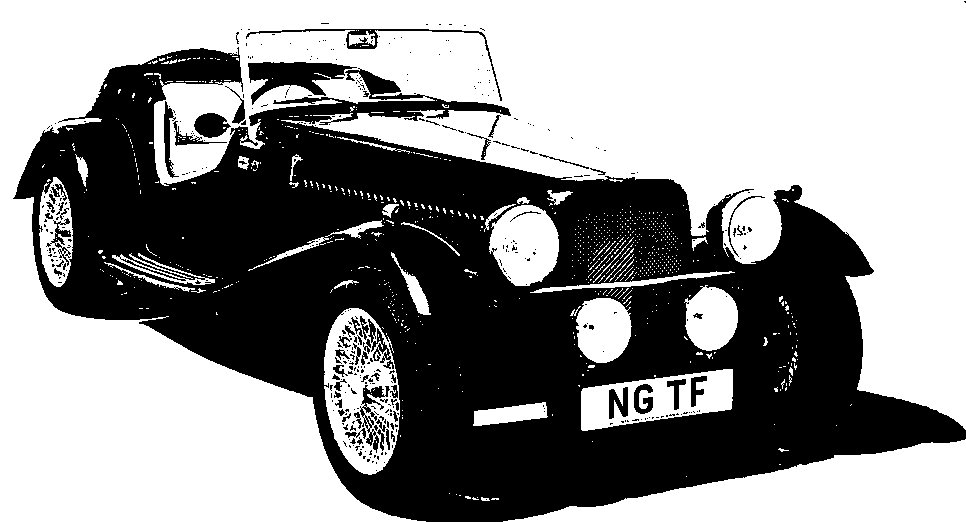
NG Kit Car
17.5 Other Electrics
Ignition Coil
The "standard" location for the coil is fixed to a bracket on the right front chassis rail. However, the space there is rather cramped and I suspect it may be susceptible to road spray too. So I decided to fit my coil on the footwell top (photo 1). The high tension lead reached easily but the low tension cables needed extending. As with the rest of the front loom, the extension is run in split convoluted tubing.
The connections for the coil were not quite correct in my version of the build manual. For the 2 wire tachometer (rev. counter) which I have, ALL the following connections are needed:
-
Double white to coil positive (12v supply)
-
Double white/black to coil negative (one of these feeds the tachometer)
-
Single white/black to coil negative (to earth via distributor contact breakers)
For the 3 wire tachometer, I believe the manual is correct and the connections are:
-
Double white/black to coil positive (12v feed from tachometer)
-
Single white/black to coil negative (to earth via distributor contact breakers)
-
Double white is NOT USED
Horns
Standard MGB twin horns (high note & low note) are used. Each is mounted on an L-shaped bracket (supplied by NG) which connects the front cross member flange to the back of the cowl's number plate surface (photo 2).
Wiring for Front Lights
For the connections under the front wings, I used bullet connectors (although I am not keen on them) and staggered their position. This enabled me to hide and protect them inside some split convoluted tubing.
The two wires going up to the right of photo 3 are for the indicator, while the four going to the left are for the headlamp unit (including side lamps). Once wrapped in the tubing, the wiring could be secured to my additional wing support bracket (photo 4, see also Front Wing Brackets).
Wiring for Rear Lights
Wiring for the rear lights was hidden and protected inside split convoluted tubing (photo 5).
Note: covers have now been added to protect the light fittings from road spray - see Rear Light Covers in modifications section.

on top of footwell

under front cowl

fitted

on top of footwell
Battery Cover
A GRP battery cover can be supplied by NG. It requires cut outs in the front to clear the inertia reel seat belt (photo 6).
The rear flange is fixed with a wing nut onto a stud. The latter was formed by fitting a machine screw into a tapped hole in the body from underneath. For the front flange I combined a screw and wing nut to give a "wing bolt". This is screwed into a tapped hole in the body from above. Both these fixings make the cover easy to remove.